- 非IC关键词
企业档案
- 相关证件:

- 会员类型:普通会员
- 地址:深圳市福田区华强北赛格科技园四栋中12楼A4座—2L
- 传真:0755-83955172
- E-mail:1282971461@qq.com
产品分类
相关产品
产品信息
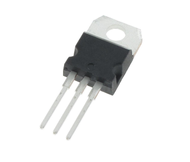
IRFB3607PbF
IRFS3607PbF
IRFSL3607PbF
Applications
High Efficiency Synchronous Rectification in
SMPS
Uninterruptible Power Supply
High Speed Power Switching
Hard Switched and High Frequency Circuits
HEXFETS
Benefits
Improved Gate, Avalanche and Dynamic
dv/dt Ruggedness
Fully Characterized Capacitance and
Avalanche SOA
Enhanced body diode dV/dt and dI/dt
Capability
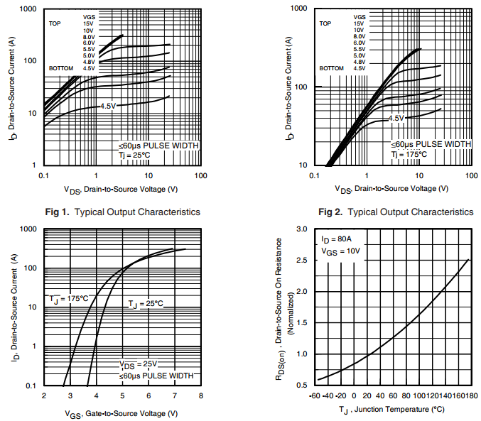
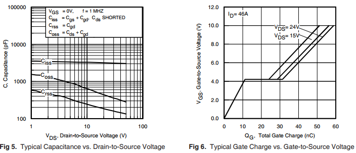
IRFB3607PbF IRFS3607PbF IRFSL3607PbF
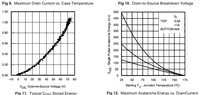
Notes on Repetitive Avalanche Curves , Figures 14, 15:
1. Avalanche failures assumption:
Purely a thermal phenomenon and failure occurs at a temperature far in
excess of Tjmax. This is validated for every part type.
2. Safe operation in Avalanche is allowed as long asTjmax is not exceeded.
3. Equation below based on circuit and waveforms shown in Figures 16a, 16b.
4. PD (ave) = Average power dissipation per single avalanche pulse.
5. BV = Rated breakdown voltage (1.3 factor accounts for voltage increase
during avalanche).
6. Iav = Allowable avalanche current.
7. T = Allowable rise in junction temperature, not to exceed Tjmax (assumed as
25°C in Figure 14, 15).
tav = Average time in avalanche.
D = Duty cycle in avalanche = tav ·f
ZthJC(D, tav) = Transient thermal resistance, see Figures 13)
PD (ave) = 1/2 ( 1.3·BV·Iav) = T/ ZthJC
Iav = 2T/ [1.3·BV·Zth]
EAS (AR) = PD (ave)·tav1
IRFB3607PbF
IRFS3607PbF
IRFSL3607PbF
IRFB3607PbF
IRFS3607PbF
IRFSL3607PbF





 询价
询价
