相关证件:
会员类型:
会员年限:13年
朱亮成 
电话:0755-83264115
手机:15889758566
18948336722
电话:0755-82710921
手机:13714022780
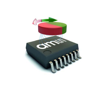


TheAS5040 is a contactless magnetic rotary encoder for
accurate angular measurement over a full turn of 360°. It is a
system-on-chip, combining integrated Hall elements, analog
front end and digital signal processing in a single device.
To measure the angle, only a simple two-pole magnet, rotating
over the center of the chip, is required. The magnet may be
placed above or below the IC.AS5040-ASST
The absolute angle measurement provides instant indication of
the magnet’s angular position with a resolution of 0.35° = 1024
positions per revolution. This digital data is available as a serial
bit stream and as a PWM signal.
Furthermore, a user-programmable incremental output is
available, making the chip suitable for replacement of various
optical encoders.
An internal voltage regulator allows the AS5040 to operate at
either 3.3 V or 5 V supplies.AS5040-ASST

• Office equipment: printers, scanners, copiers
• Replacement of optical encoders
• Front panel rotary switches
• Replacement of potentiometers
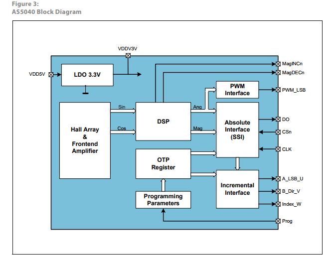
Block DiagramAS5040-ASST
AS5040-ASSTThe functional blocks of this device are shown below:
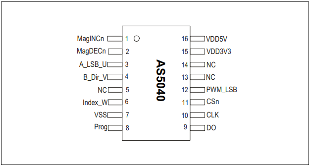
 Pin Assignment
Figure 4:
Pin Configuration SSOP16
Pin Description
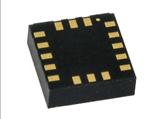
Figure 6 shows the description of each pin of the standard
SSOP16 package (Shrink Small Outline Package, 16 leads, body
size: 5.3mm x 6.2mmm; see Figure 4).
Pins 7, 15 and 16 are supply pins, pins 5, 13 and 14 are for
internal use and must not be connected.
Pins 1 and 2 are the magnetic field change indicators,
MagINCn and MagDECn (magnetic field strength increase or
decrease through variation of the distance between the magnet
and the device). These outputs can be used to detect the valid
magnetic field range. Furthermore those indicators can also be


 询价
询价